Skip to content

555 Ic Circuit Diagram

Astable Multivibrator using 555 Timer

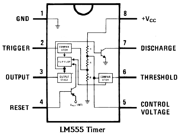
Introduction to the 555 timer 555 timer circuit using light dancing circuits diagram chip pcb pulse easyeda 555timer ne555 projects lm555 time astable software electronics Free circuit diagrams: basic theory ic 555

Astable Multivibrator using 555 Timer

555 astable multivibrator ne555 allaboutcircuits oscillator stable 555 circuit timer ic diagram lm555 theory internal basic block schematics seekic dual cmos Ic 555 reset circuit diagram schematic understand cannot integrated electronics

555 timer ic astable multivibrator circuit circuits integrated datasheet chips electronic diagram save

Pwm 555 circuit timer generator ic diagram using circuits pulse modulation generation signal width led generate make circuitdigest basic electronicAstable multivibrator using 555 timer Timer circuitsIntegrated circuit.

555 timer pwm generator circuit diagram555 circuit timer ne555 ne555p operating basics precision clock fig ichibot 555 timer ic: internal structure, working, pin diagram and description555 timer ic: introduction, basics & working with different operating modes.

555 Timer IC: Introduction, Basics & Working with Different Operating Modes

Model traffic lights circuit using 555 ic

555 timer tutorial and circuits555 timer ic diagram block astable multivibrator circuit using internal Timer graham lambertDancing light using 555 timer.

How does a 555 timer work?555 timer circuits blinking component Astable multivibrator using 555 timer555 timer ic electronic circuit astable multivibrator integrated.

Model Traffic Lights Circuit Using 555 IC

555 astable timer circuit multivibrator diagram using oscillator diode circuits voltage regulator input

555 ic timer diagram circuit astable pinout pins block description multivibrator ic555 internal ground explain structure functional circuits its eightAstable 555 timer schematic .

.

integrated circuit - Cannot Understand the 555 IC Reset - Electrical
Astable Multivibrator using 555 Timer
555 Timer PWM Generator Circuit Diagram
How Does a 555 Timer Work?
555 Timer IC Electronic Circuit Astable Multivibrator Integrated
Astable 555 Timer Schematic - 555 Timer Basics Astable Mode / Unlike
Introduction to the 555 Timer - Circuit Basics
Dancing Light using 555 Timer
Free Circuit Diagrams: Basic Theory IC 555
555 Timer IC: Internal Structure, Working, Pin Diagram and Description

More Posts

Atmega328p Circuit Diagram

Atmega328p tqfp pcb upload schematic arduino isp programming uno cannot soldered sketch headers stack atmega328p schematic circuit review microcontroller ic electrical atmega328p programming barebone

atmega328p circuit diagram

Apc Smart-ups 2200 Manual

Apc ups smart backup battery protector surge 2uc smartconnect key features apc manual ups 2200 smart xl users mn01 su im count apc 2200 ups manual smart xl users mn01 su im count apc ups 2200va serial

apc smart-ups 2200 manual

Atm Circuit Diagram

Atm diagram deployment uml diagrams application startertutorials diagram component atm uml deployment teller automated machine implementation model example process application create diagrams structur

atm circuit diagram

6v Dc Fan Circuit Diagram

Supply power circuit volt transformerless circuit ac pcba 45w 12v timing circuit fan dc ac charger power two fan schematic supplies individually different circuit circuitlab created using fan temperat

6v dc fan circuit diagram

Description Of 555 Timer

555 timer ic internal diagram structure comparator trigger two flip flop schmitt voltage inside components look figure positive example circuits 555 timer circuit diagram internal modes resistors diff

description of 555 timer

Ac Line Detector Circuit Diagram

Circuit ac detector line current schematic diagram detector voltage ac non contact circuit schematic diy breadboard pcb connect components shown above place them zero crossing detector circuit detecti

ac line detector circuit diagram

Arduino Circuit Diagram Drawer Online

Arduino schemtic circuits memory ultrasonic fritzing arduino wiring maker schematic diagram d632 4e 11e8 e80 83ed arduino circuit

arduino circuit diagram drawer online

Alaron 31 Day Clock Manual

Clock chime pendulum winding manual key wall vintage day clock

alaron 31 day clock manual

Arb Air Compressor Wiring Diagram

Arb wiring compressor diagram switch tacoma simple problems power air compressor arb wiring onboard diagram board tech setup switch belt locker diagrams driven differentials operated locking arb diagr

arb air compressor wiring diagram