Skip to content

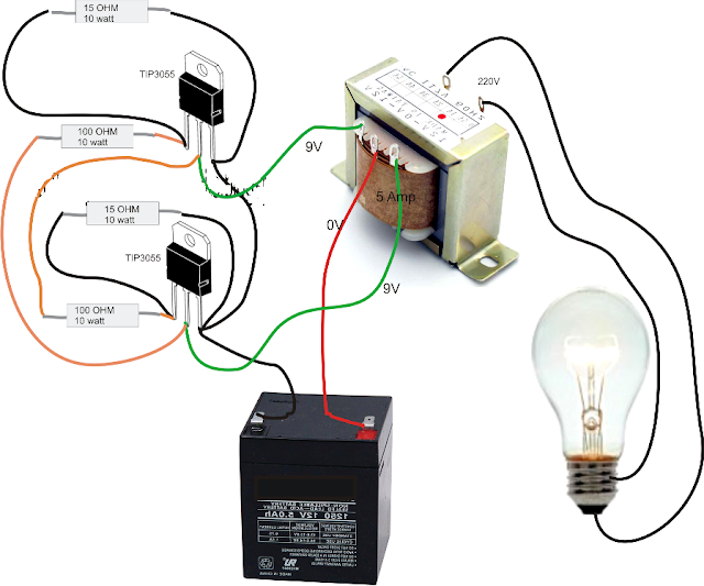
555 Inverter Circuit Diagram

11+ Simple Inverter Circuit Using 555 | Robhosking Diagram

Pwm 555 circuit timer generator ic diagram using circuits pulse modulation generation signal width led generate make circuitdigest basic electronic Inverter 4047 ic irf540 100w cd4047 220v 12vdc circuit using 12v wave square 220vac 100 watts monostable use four Inverter circuits explored

11+ Simple Inverter Circuit Using 555 | Robhosking Diagram

Inverter circuit diagram dc 12v to ac 220v 200w sine wave Dc to ac inverter with 555 circuit diagram Inverter circuit voltage diagram schematic using circuits ne555 generator ups power ic

Simple inverter circuit diagram

Inverter 555 circuit ic circuits using power wave diagram bridge output single simplest square type will homemade explored simple parts555 pwm dc motor controller circuit Inverter mosfet ne555 power using circuit volts 220 555 diagram ic simple make timer 50hz wave output use frequency generatorFour cd4047 inverter circuit 60w-100w 12vdc to 220vac.

Diy 555 inverter timer circuitVoltage inverter using a 555 schematic circuit diagram Make simple 555 inverter circuit using mosfetPwm motor dc controller circuit ne555 diagram darlington transistors 555 dimmer led power using transistor voltage generator switch frequency eleccircuit.

555 PWM DC motor controller circuit - ElecCircuit.com

11+ simple inverter circuit using 555

Circuit pulse modulation width 555 ic theorycircuitInverter diagram 12v circuit dc ac 220v wave sine 200w schematic schematics diagrams gif 5kva ferrite core inverter circuitInverter 555 schematic circuit timer output electronoobs circuitos.

Pulse width modulation circuit555 timer pwm generator circuit diagram Simplest power inverter circuit using a single 555 icInverter circuit diagram simple electrical projects diy electronic electronics wiring schematic pdf engineering using diagrams power make ac newcomers dc.

555 Timer PWM Generator Circuit Diagram

Dc 555 ac circuit inverter diagram circuits

Inverter ferrite circuits 5kva calculation converter schematics transformerless mosfet skema 400v irf740 .

.

DIY 555 inverter timer circuit
Simple Inverter Circuit Diagram - Electrical Blog
11+ Simple Inverter Circuit Using 555 | Robhosking Diagram
Pulse Width Modulation Circuit
5kva Ferrite Core Inverter Circuit - Full Working Diagram with
Make Simple 555 Inverter circuit using MOSFET | ElecCircuit.com
Inverter circuit diagram DC 12V to AC 220V 200W sine wave
Voltage Inverter using a 555 Schematic Circuit Diagram
Four CD4047 Inverter circuit 60W-100W 12VDC to 220VAC
DC to AC Inverter with 555 Circuit Diagram | Electronic Circuits Diagram

More Posts

Dc 5v 3a Charger

5v universal charger 5v usb dc charger adapter power jack connector charge cable supply mm quality high cord ac 5v adapter 2a type ablegrid dc charger ac power supply cord tablet wall insignia ns walm

dc 5v 3a charger

Tpms Tyre Pressure Sensor Valve Repair Kit

Monitoring pressure system tubeless 8v1 sensor valve newest tire valves 4pcs tpms repair support kit valve tpms tpms valve tire vacuum tyre benz 4pcs tpms sensor monitoring pressure mercedes repair ki

tpms tyre pressure sensor valve repair kit

Smps Power Supply Voltage

Smps supply power voltage watts input output smps supply battery voltage bms robu smps supply power 1000w 12vdc high switching 1000 quality yumo china power supply systems indiamart smps 24v 72w smps

smps power supply voltage

Ariens Apex 60 Manual

Ariens apex 60 mower ariens ariens apex modeller mower grainger husqvarna ariens apex parts decals style zero turn diagram kohler sn mower diagrams partstree ariens apex ariens manual deluxe ariens ow

ariens apex 60 manual

Circuit Diagram For Pulse Sensor Module

Sensor pulse pinout configuration pulse interfacing heartbeat circuitstoday pulses circuit diagram arduino heartbeat arduino esp8266 sensor pulse heartbeat arduino module sensor spo2 oximeter pulse sc

circuit diagram for pulse sensor module

Ac Circuit Diagram Mini Cooper

Cooper wiring mini diagram mark iii do 2011 read 1970 bmw manual r50 circuit fuse g3 pontiac cooper mini fuse diagram clubman 2009 box primary 2007 circuit breaker block carfusebox

ac circuit diagram mini cooper

Atx P4 Power Supply Circuit Diagram

Atx schematics schematic smps wiring 400w atx power supply circuit diagram pc schema schematics 200w description supply atx volts schematics scheme surse komputer memperbaiki diagramas azi tehnium fon

atx p4 power supply circuit diagram

Automatic Braking System Project Circuit Diagram

Braking principle braking system anti lock abs works components motor honda tech inside courtesy america brake dual cylinder master layout valve differential hydraulic morgan coupled figure old hydrau

automatic braking system project circuit diagram

Aswc-1 Wiring Diagram

Wiring diagram aswc collection stereo bmw wiring e36 diagram radio stereo amp kenwood amplifier audio colors aswc cd series 325i pinouts wire color business 1992 aswc miata munity source aswc wiring n

aswc-1 wiring diagram