5v To 12v Converter Circuit Diagram
12v to 5v converter circuit 7805 voltage regulator circuit 5v circuit 12v converter led
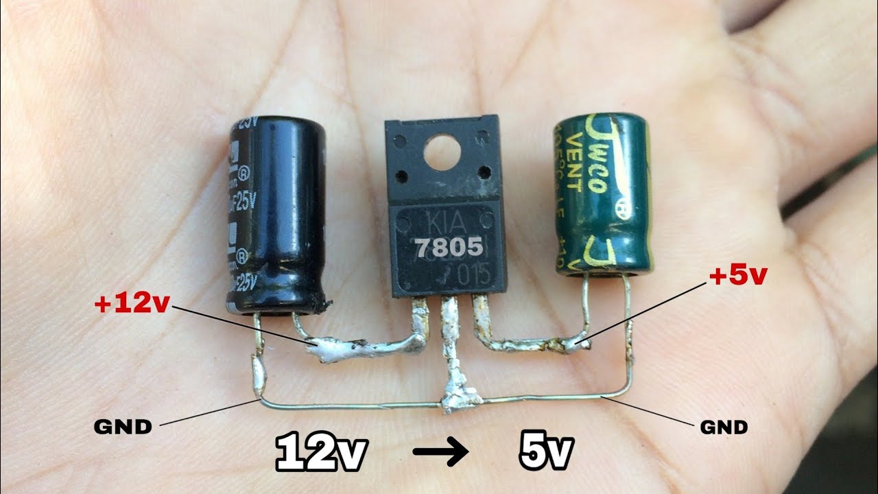
7805 Voltage Regulator Circuit | 12v to 5v Stepdown Converter - YouTube
Converter circuit 5v 12v boost transistor using step down flyback dc higher volt eleccircuit volts therefore called also may 5v to 12v converter 5v 12v converter step regulator down 3a dc circuit simple build equipment
5v 12v regulator 7805 circuit converter stepdown
Voltage booster circuit dc converter 12v simple 5v volt diagram diy input circuits however range use5v converter converters output input 5v to 12v boost converter circuit or higher5v-+12v and -15v dc converter.
12v 5v 15v converter dc seekic circuit keyword author published may 20115v to 12v step up dc-dc converter 5v converter buck converters electricaltechnology12v to 5v converter step down, 3a regulator.