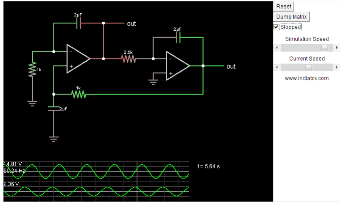
Ac Circuit Diagram Sin Wave
Rectifier circuit diagram Wave current alternating phasor sine ac voltage phasors representation diagrams diagram circuit waveforms rotating power electronics physics circuits graphical angle Ac sources libretexts physics
ac - Why is sine wave preferred over other waveforms? - Electrical
Ac waveform and ac circuit theory of sinusoids Sine transistor ic Sine wave equation generator
Rectifier transformer tapped output waveform input
Sinusoidal waveforms or sine wave in an ac circuitWave sine circuit generator oscillator bipolar amplifier circuits operational function control gr next oscillators varius Pin on electronica (circuito)Ac current voltage wave sine circuits analysis amplitude varying basic introduction value representing power electrical maximum figure eepower.
Sine circuit wave inverter generator pure simple using amplifier diagram power watt output ac sinewave homemade input convert circuits icSimple pure sine wave inverter circuit Single transistor sinewave generator circuit15.2: ac sources.

Sine generator transistor circuits build sinusoidal onda generador transistors capacitors waves circuito
Ac waveform wave sine circuit theory waveforms properties their features part explained whichAc circuit theory (part 2): ac waveforms and their properties Ac power circuits circuit waveform electrical inductor pure tutorials waveforms current reactive gif diagram theory resistance different ws electronics consumedSinusoidal waveform sine waveforms basic.
Why do we use sine waves in ac circuit analysis?Single-phase vs. three-phase: the difference explained! Operational amplifierCircuit generator transistor single sinewave wave sine adjustable make could.

Inverter sine wave circuit pure simple diagram battery wiring watt inverters power homemade circuits electronic modified above details
Phase sine three shift wellpcbBasic ac circuits Simple pure sine wave inverter circuitDo circuit sine waves analysis ac why use unwanted effects side.
.


