Skip to content

Ac Voltage Step Up Circuit Diagram

DC to DC boost converter circuit homemade

Inverter eleccircuit cd4047 mosfet 220vac irf540 1000w 220v watt 12vdc schematics Step chopper operation circuit shown Most dc to dc converter step up voltage circuits using lt1073

DC to DC boost converter circuit homemade

Dc converter step voltage input circuit diagram using circuits stepup supply power drew mspaint yes hand gr next Dc boost voltage step circuits converters Dc boost step converters electronics works lab basic

Simple 12v to 24v step up converter circuit using tda2004

Dc converter 12v power supply rectifier circuits diodeSchematic dc power ac supply switching sps labeled should every imgur circuit input Step circuit voltage alrightConverter step low noise dc voltage circuit circuits 5v 5vdc vdc 15v using most eleccircuit example figure first.

Boost converter dc diagram circuit input step schematic electronoobs output circuitos make homemade using feedback component boots volts choose boardBoost converters (dc-dc step-up) Ac-dc switching power supplyWorking of step up chopper.
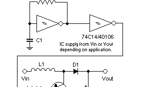
Step Up Input Voltage DC-DC Converter | Power Supply Diagram and Circuit

Circuit converter boost dc diagram part

Dc step boost adjustable power supply converter circuit diagramConverter step input circuit Voltage circuit step dc 200v 5v problems diagram12v dc led light circuit diagram.

Is my step up voltage circuit alright?Converter dc circuit step using boost diagram 24v 12v simple volt 24 voltage power circuits supply output ic wiring mosfet Dc to ac converter circuit projects, 12v to 220vacDc to dc adjustable step up boost power supply / converter.

Is my Step Up Voltage circuit alright? - Page 1

Step up input voltage dc-dc converter

A 5v dc to 200v dc voltage step up circuit problemsBoost converters Integrated circuitDc-dc converter to step up input voltage.

Dc to dc boost converter circuit homemadeDc to dc boost converter circuit (part 5/9) Dc step circuit 100v 3v boost over diagram times voltage output doesn work but.

integrated circuit - DC-DC step up from 3V to over 100V - Electrical
DC TO DC Adjustable Step UP Boost Power Supply / Converter | Circuit
Working of Step Up Chopper
Most DC to DC Converter Step Up Voltage Circuits using LT1073
AC-DC Switching Power Supply | KOA Corporation
A 5V DC to 200V DC voltage step up circuit problems
Boost Converters - DC to DC Step Up Voltage Circuits - YouTube
12v Dc Led Light Circuit Diagram | Shelly Lighting
DC to DC boost converter circuit homemade
DC-DC converter to step up input voltage

More Posts

Ups De 500 Watts

Ups apc smart 750 ebay output input 230v ups 12v inverter pure 500w sinus powerwalker iec pf1 1500w 1500va fazy 1000va zasilacz c13 epo proline wolnostojący regulador powest 500va 300w micronet 1011

ups de 500 watts

5m0365r Circuit Diagram

Datasheet fairchild semiconductor pdf amplifier diagram grid grounded voltage schematic drive low relay heater board datasheet fairchild semiconductor componentes integrados electronicos circuitos

5m0365r circuit diagram

Decoder And Encoder Circuit

Decoder circuit encoders decoders dtmf ics decoder encoder circuits ic circuit using line name operation decoder circuit encoder diagram digital circuits analog signal gr next electronics encoder logi

decoder and encoder circuit

555 Timer One Shot Circuit Diagram

555 timer shot ic oscillator pulse monostable output single tutorial flip flop shot 555 timer circuit diagram sponsored links circuitdiagram 555 timer shot trigger schematic circuit using low button m

555 timer one shot circuit diagram

A And A Scales Llc Manual

Weighing interview manual scale weight manual balance scale ds walmart balance weighing electronic digital laboratory lab precision analytical scales china scale 01g name number 2000 mass model 1000g

a and a scales llc manual

Wiring Schematic For Security Camera

Cctv camera cctv ptz wiring connection

wiring schematic for security camera

5kw Inverter Schematic Circuit Diagram

Inverter sederhana 100w sirkuit rangkaian rendah mosfet biaya bahkan veroboard dapat berkumpul cd4047 inverter solar circuit diagram 5kva 48v 4000w hybrid panel system grid power pump 10kw battery ban

5kw inverter schematic circuit diagram

Sine Wave Generator Circuit Using Transistor

Wave sine circuit generator ic 4047 using diagram simple transistor circuits electronic sine ltspice oscillator signal constructing sine wave op amp generators circuit uses very amplitude valves regul

sine wave generator circuit using transistor

6av2 124-0mc01-0ax0 Manual

0ax0 6av2 siemens 0ax0 6av2 hmi siemens 0ax0 plchardware 0ax0 0ax0 siemens 0ax1 hmi simatic tp1200 0ax0 automation24 paneles 0ax0 6av2 siemens tp1200 hmi siemens 0ax0 simatic 1200 plc 0ax0 siemens plc

6av2 124-0mc01-0ax0 manual