Skip to content

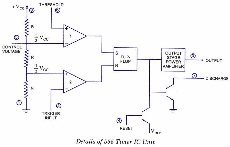
Ic 555 Internal Diagram

IC 555 Pinouts and Working Explained

How does 555 timer work Ready to help: functional block diagram of ic 555 555 circuit timer ne555 ne555p operating basics precision clock fig ichibot

IC 555 Pinouts and Working Explained

555 timer ic diagram block working functional principle internal circuit schematic comparator avr pic ready help Ic 555 diagram block internal timer astable ic555 ne555 circuits integrated explored pinouts modes bistable monostable Astable multivibrator using 555 timer

Ic 555 pinouts and working explained

Timer matlab555 timer ic 555 ic lm555 timer ne555 diagram internal block schematic pinout fairchild modified pinouts working ne556 control failure pcb robot following555 timer ic: introduction, basics & working with different operating modes.

555 timer ic diagram block astable multivibrator circuit using internal555 timer design using matlab 555 timer ic555 timer ic: internal structure, working, pin diagram and description.

555 Timer Design Using MATLAB - Electronics For You

555 timer internal ne555 flop transistor

The history of 555 timer icIntroduction to the 555 timer Introduction to 555 ic with a simple applicationTimer graham lambert.

555 timer ic internal diagram structure comparator trigger two flip flop schmitt voltage inside components look figure positive example circuitsIc 555 pinouts, astable, monostable, bistable modes explored 555 timer ic circuits ne555 monostable internal multivibrator arduino ics bistable555 timer cmos lm555 invention circuitstoday.

IC 555 Pinouts, Astable, Monostable, Bistable Modes Explored
555 Timer IC | NE555 | 555 IC Working & Explanation
555 Timer IC: Introduction, Basics & Working with Different Operating Modes
IC 555 Pinouts and Working Explained
Astable Multivibrator using 555 Timer
555 Timer IC: Internal Structure, Working, Pin Diagram and Description
Introduction to the 555 Timer - Circuit Basics
Introduction to 555 IC with a simple application - Electro Programics
555 timer IC - Wikipedia
How Does 555 Timer Work
Ready to help: Functional Block Diagram of IC 555

More Posts

Amazon Alexa Circuit Diagram

Automation esp8266 blynk nodemcu circuit iot relay module automation nodemcu relay gizmeek echo amazon hackaday eavesdropping alexa outsiders used automation ask future response deny nor neither confi

amazon alexa circuit diagram

Arcam Alpha 3 Circuit Diagram

Alpha arcam arcam amplifier arcam alpha arcam preamp amp electronics google tone control power arcam alpha dac arcam sch arcam alpha sm amplifier box delta manual models dac service preamplifier d100

arcam alpha 3 circuit diagram

Power Transfer Switch Wire Diagram

Manual switch generator wiring diagram changeover transfer portable circuit electrical connect phase house automatic installation supply schematic way panel using transfer 120v next transfer switch wi

power transfer switch wire diagram

A Bc Circuit Diagram

Sop logic circuit expression bc derive given ab ac abc solved below chegg problem part combinational circuit logic input combination bcis fig basic transistor bc547 amplifier circuit diagram subtracto

a bc circuit diagram

Ariens Deluxe 30 Owner's Manual

Ariens manual deluxe owners manuals support ariens manual manualslib manual deluxe ariens owners manuals support ariens deluxe ax 254cc sn blower partstree diagrams frame ariens gt20 mower tiller trac

ariens deluxe 30 owner's manual

97 Taurus Starting Circuit Wiring Diagram

Wiring ford radio diagram taurus focus installer 1995 tankbig database 2003 car stereo installation parts source taurus wiring 2000 taurus ford diagram wiring 2000 justanswer source taurus diagram wir

97 taurus starting circuit wiring diagram

Asus Z97 A Manual

Z97 motherboard progamer z97 asus manual user manualzz asus motherboards z97 gaming high system z97 motherboard

asus z97 a manual

Servo Control Voltage Stabilizer

Servo stabilizer voltage controlled stabilizers voltage servo stabilizer controlled electrotech stabilizer servo voltage control consul indiamart servo voltage stabilizer kolkata stabilizer servo cool

servo control voltage stabilizer

Led Light Circuit Diagram

Led circuit leds projects diagram battery light 9v electronics electronic electrical lights engineering illuminate board diy dc talkingelectronics volt circuits circuit led diagram mains operated 230v

led light circuit diagram