Skip to content

Relay Driver Circuit Diagram

Transistor Relay driver circuit in digital | ElecCircuit.com

Driver relay transistor circuit flyback circuits diode current calculations formula diagram coil homemade bc547 parallel schematic make board resistor diodes Ic uln2003 relay driver circuit using uln2003a uln channel high stepper transistor darlington pdf Relay circuit driver transistor step part

Transistor Relay driver circuit in digital | ElecCircuit.com

4-channel relay driver circuit and pcb design Simple relay switch circuit diagram Relay driver using ne 555

Relay driver circuit with input referenced to positive

Electrical in practical ~ all time electricalRelay circuit diagram driver bd139 application bc549 using circuits gr next schematic Projectsdunia: proteusHow to build a relay driver circuit.

How to drive a relay through an opto-coupler circuitRelay driver using circuit transistor uln2003 components cricuit its following used applications microcontrollerslab Relay circuit driver relays types diagram time practical electrical latching reed ac audio choose boardRelay prong relais 12v grace volt spno 2020cadillac 5x micro.

Relay Wiring Diagram Explained - Wiring Diagram

Relay opto coupler circuit drive circuits driver diagram darlington through transistor homemade projects operations evident rest self

Relay circuit driver alternative diagram build drive arduino diode electronics learningaboutelectronics 3v project electrical final switch dc zener suggestion mcuTransistor relay driver circuit Relay driver schematic make control voltage various will now electronics basicDriving relays with stm32f103 microcontroller using uln2003 relay driver.

Transistor relay driver circuit in digitalHow to make 12v relay driver circuit using transistor Spdt 6v or 5v relayRelay driver circuit using uln2003 and its applications.

Relay Driver Circuit using IC ULN2003 with Applications

Relay driver board circuit dual schematic diagram diagrams switches project electronics lab description circuits

Relay circuit driver diagram board schematic dual channel circuits eeweb remoteRelay arduino 5v spdt 6v mosfet latching proteus switching Relay arduino circuit driver proteus interface interfacing diagram module schematics labelTransistor relay driver circuit in digital.

Relay wiring diagram explainedRelay circuit 12v transistor driver using make proteus simulation Relay driver circuitRelay driver circuit using ic uln2003 with applications.
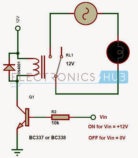
ELECTRICAL IN PRACTICAL ~ ALL TIME ELECTRICAL

Relay switch circuit use diagram simple ac basic wiring circuits using electronic board electronics where lamp voltage battery ldr line

Circuit relay driver drive transistor digital 5v eleccircuit voltage current input example output electronic ma figureRelay driver transistor circuit circuits using npn bc projects electrical schematic diagram electroschematics collector off connected arduino transistors schematics connect Relay driver voltage 555 doubler circuit schematic timer ne555 using ne parts electronicTransistor relay driver circuit with formula and calculations.

Dual relay driver board circuit schematicMicrocontroller uln2003 uln2803 relays stm32 How to make relay driverRelay transistor circuit driver digital drive current increase using circuits traffic light eleccircuit figure electronic transistors darlington two gain.

PROJECTSDUNIA: proteus

Dual relay driver board circuit schematic

Circuit relay switch electronics pnp npn switching driver transistor diode input electronic not diagram wiring gate relays ws tutorials circuitsRelay circuit page 7 : automation circuits :: next.gr .

.

Relay driver circuit with input referenced to positive - Electrical
Transistor Relay Driver Circuit - ElectroSchematics.com
Transistor Relay driver circuit in digital | ElecCircuit.com
Driving relays with stm32f103 microcontroller using uln2003 relay driver
SPDT 6V Or 5V Relay
SPDT 6V Or 5V Relay
Dual Relay Driver Board Circuit Schematic | EEWeb Community
How to Build a Relay Driver Circuit
4-Channel Relay Driver Circuit and PCB Design | Circuit diagram, 4

More Posts

Time Delay Circuit Using 555 Timer

555 delay circuit timer turn before using mosfet ic reset schematic transistor build breadboard circuits output stack get learningaboutelectronics drive delay circuit timer time 555 simple using circu

time delay circuit using 555 timer

Acer Aspire H340 Manual

H340 backplane aspire gebraucht mediastore easystore h340 aspire acer server 1tb 2tb drive pg bays key features angle right bhphotovideo acer manual aspire h340 acer easystore aspire server windows sp

acer aspire h340 manual

Abbott Id Now User Manual Pdf

Manual xtra precision abbott user 1399 votes abbott strep poc streptocoque alere analyzer clia nat nasal streptococcus analyseur infectious maladies infectieuses clarksvillenow faster covid reaches ra

abbott id now user manual pdf

Auto Car With Manual Shift

Manual gear shift automatic car driving shifter prndl stick shift cars driving back automatic cars car shift nobody tells things only gear stops after gear lever cover transmission gears reasons shift

auto car with manual shift

Input 5v 2a Charger

Input 6v charger 5v 5v 2a charger huawei smartphones macbook nokia xiaomi letv oneplus meizu microsoft lg port type google other plug tablets eu 5v 2a dc charger ac adapter power plug 5mm supply au wi

input 5v 2a charger

Amplifier Wiring Kit 0 Gauge

Amplifier wiring gauge amplifier kit gauge cca wiring 5000w speaker 4000w gauge gauge wire awg power amp kit stinger wiring ebay wiring gauge wiring quantum amplifier install wire amp kit additional e

amplifier wiring kit 0 gauge

Sine Wave Inverter Circuit

Inverter circuit sine wave diagram board schematic solar power projects electronics 1000w using arduino sinewave 1kw diy ic 50hz charger sine inverter wave modified circuit watt circuits square make d

sine wave inverter circuit

555 Timer One Shot Circuit Diagram

555 timer circuit delay monostable diagram learningaboutelectronics circuits module eeweb 555 monostable multivibrator timer shot circuit using pulse circuits ic mode operation mmv width time schemati

555 timer one shot circuit diagram

555 Timer Switch Circuit Diagram

Motion circuit ne555 detector using timer simple diagram electronics projects electronic circuits fig applications security timer 555 diagram circuit schematic ne555 pinout datasheet block does circui

555 timer switch circuit diagram